Introduction
As of mid-2023, this design is still mostly conceptual and largely consists of fragments of partially-completed ideas in RTL. There are no synthesizable artifacts, and this will probably be the case for some time.
This project is a vehicle for exploring the following questions:
- How are modern [superscalar, out-of-order] microprocessors implemented?
- How do you create a behavioral description of these machines in RTL?
- What does it take to physically implement these machines?
Currently, ZNO is a RISC-V machine designed around the RV32I base integer
instruction set. This seemed like sufficient ground for exploring many
of the problems involved in the design of modern machines.
Other aspects of the RISC-V ISA can probably be added after the
overall design has stabilized somewhat.
Rough Overview
The ZNO core is split into three pieces:
- The frontend (for dealing with control-flow)
- The midcore (for managing state)
- The backend (for dealing with data-flow)
About Chisel
ZNO is written in Chisel,
an HDL embedded in Scala. Chisel internally represents designs with
FIRRTL, which may be lowered
into other representations (like Verilog) via CIRCT.
Testing/Simulating the Design
Chisel also includes a framework for writing tests (chiseltest).
In the future, it will probably be necessary to explore other ways of
simulating and testing designs.
Specifically, CIRCT's arc dialect provides a representation for simulating
circuits which can be lowered into LLVM IR!
CIRCT provides an experimental tool (arcilator) for this, although FIRRTL
needs to be lowered into the hw dialect for this to work.
At the moment, arcilator can be used to generate simple C++ bindings
(see tools/arcilator` in the CIRCT tree for details on this).
It's easy to imagine that in the future, the FIRRTL dialect will be able to
represent user-defined types (Chisel bundles). Presumably at some point,
this information can be lowered into hw and used by arc (or other
tooling) for creating a nice ergonomic interface to the simulated state.
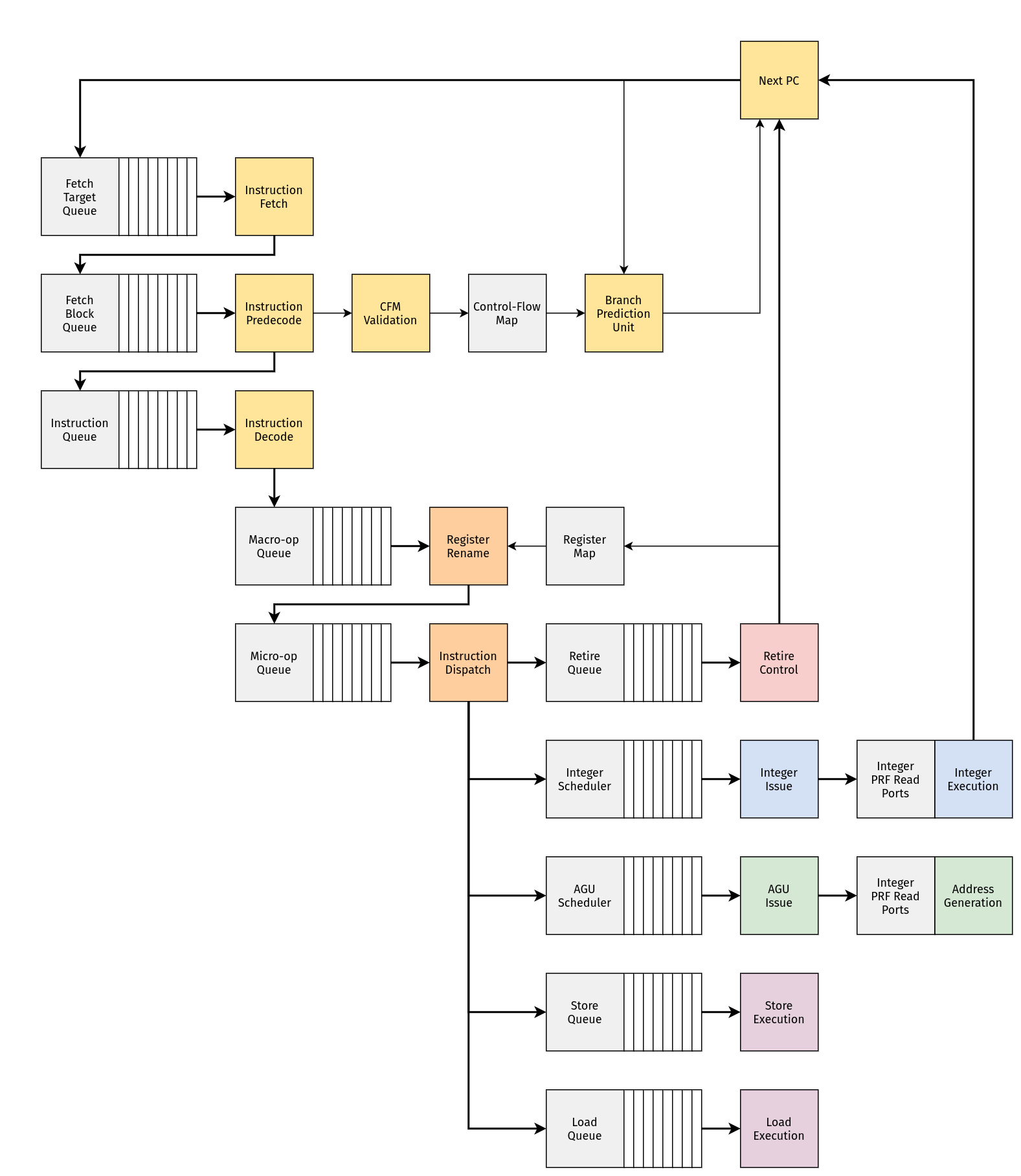
ZNO Frontend
The front-end of a modern microprocessor is mostly concerned with keeping a constant stream of instructions moving into the machine.
Branch Prediction attempts to predict the direction/target of individual control-flow instructions by caching branch target addresses and tracking the history of previous branch outcomes.
Next-Fetch Prediction attempts to predictively guide instruction fetch by caching branch predictions and associating them with the names of previously-fetched blocks.
Instruction Fetch retrieves instructions from memory.
Instruction Predecode extracts immediate data/control bits from instructions, and attempts to discover control-flow instructions early in the pipeline.
Instruction Decode transforms instructions into macro-ops.
Control-flow
A control-flow event occurs when frontend must move to a new point in the instruction stream. A unique point in the instruction stream is always represented by a program counter value.
A control-flow event indicates the start of the instruction pipeline, and results in the instruction fetch unit bringing the the appropriate fetch block into the machine.
Speculative Events
Ideally, control-flow events occur every cycle in order to keep the pipeline filled with instructions. However, in pipelined machines, there is an inherent latency associated with architectural changes in control-flow: instructions take multiple cycles to move through the pipeline.
In order to compensate for this, changes in control-flow may be predicted and may occur speculatively.
Control-flow events are called speculative when the next set of instructions are part of a predicted path through the instruction stream.
Speculative events are generated from a branch prediction pipeline which is partially decoupled from the instruction pipeline.
Architectural Events
Control-flow events are called architectural when the next set of instructions are guaranteed to belong to the path through the instruction stream. For instance:
- When execution begins at the reset vector, the architectural path continues at the reset vector
- When a faulting instruction retires and causes a precise exception, the architectural path continues at the location of an exception handler
- When a branch or jump instruction retires, the architectural path continues at the appropriate branch target address
- When an entire block of instructions retires without causing any of the events listed above, the architectural path must continue at the next-sequential block of instructions
Architectural events are generated from the retire control unit.
Fetch Blocks
It's useful to think of the instruction stream as a control-flow graph where the edges are control-flow operations (jump and branch instructions), and the nodes are basic blocks which:
- Begin with an instruction which is the target of a control-flow operation
- End with a single control-flow operation (whose target is necessarily the start of a basic block)
Note that these are distinct from fetch blocks. A basic block might consist of multiple sequential fetch blocks. Or conversely, a single fetch block might have multiple basic blocks.
There's a sense in which we ideally want to maintain a cached version of something like a control-flow graph:
- When entering a basic block, how many sequential fetch blocks until we reach the end of the basic block? These can be immediately queued up for fetch.
- When we reach the last fetch block within a basic block, which instruction is terminal, and what is the address of the next basic block?
The instruction stream is quantized in terms of fetch blocks which correspond to the smallest addressible elements in instruction memory (typically, a line in some first-level instruction cache).
Next-Fetch Prediction
Ideally, instruction fetch is constantly producing an uninterrupted stream of fetch blocks which contain the correct, architecturally-relevant path. In order to approach this goal, each address sent to instruction fetch must also be subject to a next-fetch prediction.
Ideally, this occurs immediately when the machine obtains the next program counter value - otherwise, pipeline bubbles will occur as the machine becomes starved for instructions.
"Control-flow Map" (CFM)
- This is a somewhat aggressive solution?? There's probably a more relaxed version of this where we only handle certain "easy" cases.
- This can probably be used to store certain predictions alongside branch information
- To what degree do we want speculative control-flow events to be subject to next-fetch prediction?
- You can probably use this to create some kind of basic-block map by counting fetch blocks which contain no branches?
A control-flow map (CFM) is indexed by fetch block address and stores previously-discovered control-flow information about the contents of a fetch block. When a fetch block contains branches, a corresponding CFM entry may be filled by the output of instruction predecode.
The CFM is used to predict the existence of an instruction within a fetch block that will result in a control-flow event and predict the associated target address. In this way, a CFM entry can be used to obtain the address of the next-expected fetch block while the previous is being fetched.
-
All control-flow events have an associated target (program counter value). The corresponding fetch block address is used to access the CFM while simultaneously being sent to the instruction fetch unit.
-
When a CFM miss occurs, an informed prediction cannot be made in-parallel with instruction fetch.
-
When a CFM hit occurs, the contents of the entry are used to make a new prediction in parallel with instruction fetch. This may involve accessing storage for other branch prediction structures.
-
After instruction fetch and predecode have completed, the contents of a CFM hit are validated against the newly-predecoded fetch block. If predecode output does not match the branches cached by the CFM entry, the entry must be updated to reflect the fact that the contents of the fetch block have apparently changed. This must also invalidate any prediction made with the now-invalid cached branch information.
Instruction Fetch
For now, we're assuming that all addressing is physical - totally ignoring the existence of a memory-management unit (MMU) that handles virtual addressing.
In modern machines, instruction fetch typically targets a first-level instruction cache, and fetch blocks correspond to first-level cache lines (or half cache lines). Moreover, modern machines often include prefetch logic for opportunistically moving data upwards in the cache hierarchy.
For machines with an virtual addressing, instruction fetch would also need to resolve a virtual address by interacting with an MMU. Virtual memory is typically mapped with multiple levels of page-tables (and varying page sizes). An MMU typically includes translation lookaside buffers (TLBs) that cache previous virtual-to-physical translations. On top of that, TLB maintainence is typically supported by dedicated hardware (ie. a hardware page-table walker and dedicated caches for paths through the page-tables).
First-level caches are typically virtually-indexed and physically-tagged in order to allow address translation and cache indexing to occur in parallel.
A fetch block address is sent to the instruction fetch unit, which performs a transaction with some instruction memory device. The instruction stream is quantized in fetch blocks, which are the smallest addressable elements in an instruction memory.
The size of a fetch block constrains the superscalar width of the machine. For now, we assume that a fetch block corresponds directly with the width of the pipeline (ie. for an 8-wide RV32I machine, a 32-byte fetch block).
Having the fetch block width coincide with the superscalar width is only reasonable if we can keep instruction fetch in a state where it is continuously streaming in blocks that lie along the correct architectural path?
Instruction Predecode
Some other questions that we probably want to answer with information gathered during predecode:
- If there are no branches, this fetch block is expected to always fall through to the next-sequential fetch block (ignoring the possibility of an exception)
- Does a branch target lie inside/outside this fetch block?
- Despite the existence of branch instructions, is it still possible for this fetch block to fall through to the next-sequential fetch block?
After completing a transaction, the fetch unit passes a fetch block to the predecoders. There is one predecode unit for each instruction in the block. Each predecode unit determines the following:
- The immediate encoding format
- The fully-expanded 32-bit immediate offset used to calculate a branch target
- Whether or not an instruction is a control-flow operation, ie.
- An unconditional jump (
JAL) - An unconditional direct jump (
JALR) - A conditional branch (
B{EQ,GE,GEU,LT,LTU,NE}) - A call (
JALwhererd == x1) - A return (
JALRwherers1 == x1)
- An unconditional jump (
This allows for control-flow instructions to be discovered shortly after fetch. Predecode output flows into the branch prediction pipeline, where it is used to [in]validate a previous prediction made for the corresponding fetch block.
It'd be nice to extract all immediates up-front here. This makes a nice separation between "predecode handling immediate operands" and "decode handling register operands." However, this amounts to a lot of wires (a full 32-bit immediate for each instruction in a fetch block), even before we completely decode the instruction. On top of that, these need to be stored somewhere.
Instruction Decode
Since all encodings in RV32I are 32-bit, the process of decoding instructions is dead-simple. However, compared to other kinds of machines, the code density is not ideal: programs occupy more space as a result of this.
In RISC-V, the extension for 16-bit compressed instructions is really the only way to mitigate this. This also ideally means implementing some kind of macro-op fusion, where we combine some instructions into a single operation.
In this context, all RISC-V instructions (for RV32I) have a 32-bit encoding. Each decoder expands an instruction into a set of signals called a macro-op (or "mop").
For now, we assume that there is one decoder for each instruction in a fetch block. The resulting block of macro-ops is called a decode window (or just "a decoded block").
About RISC-V Instructions
For RV32I, there are very few fundamental kinds of instructions:
- There are simple integer arithmetic/logical operations
- There are conditional branches
- There are direct and indirect unconditional jumps
- There are memory operations (loads and stores)
Notice that all of these ultimately involve an integer operation:
- Load/store addresses must be calculated with addition
- Jump/branch target addresses must be calculated with addition
- Conditional branches must be evaluated by comparing two values
With that in mind, the only real difference between these instructions is how the result of the integer operation is used. For instance:
- For simple integer operations, the result is written to the register file
- For conditional branches, there are two integer operations:
- One result (comparing
rs1andrs2) determines the branch outcome - The other result (
pc + imm) determines the target address
- One result (comparing
- For jumps, the result (
pc + imm) determines the target address - For memory operations, the result (
rs1 + imm) determines the target address
This means that RV32I instructions have a natural decomposition in terms of:
- An integer operation
- The set of operands
- Some kind of side-effect involving the integer result
About Macro-ops
A macro-op corresponds to a single instruction which has been decompressed into a set of control signals. In general, a macro-op should capture the following pieces of information:
- The type of underlying operation (integer, control-flow, load/store)
- A particular integer operation (if one exists)
- A particular control-flow operation (if one exists)
- A particular load/store operation (if one exists)
- The types of operands (register, immediate, zero, program counter)
- The architectural destination and source registers
- Whether or not the instruction produces a register result
- Immediate data and control bits (if any exists)
Branch Prediction
Branch Target Prediction
A branch target buffer (BTB) is keyed by the program counter value, and caches the previously-resolved target/s of a branch. The BTB is used to predict the target of a particular branch instruction.
Branch Direction Prediction
A branch history buffer (BHB) is keyed by the program counter value, and records a history of previously-observed branch directions. The BHB is used to predict the direction of a branch instruction.
ZNO Midcore
Register Renaming rewrites macro-ops and their operands with the goal of revealing true data dependences between instructions.
Instruction Dispatch is responsible for releasing macro-ops to the out-of-order backend of the machine, and for managing the state used to maintain/recover the original program order.
Register Renaming
Without aliasing between architectural storage locations, a set of instructions can be easily rearranged into a dataflow graph: think of instructions as nodes in the graph, and their read-after-write (RAW) dependences as edges. This makes it obvious which instructions can be completed in parallel with one another, and which instructions must wait for others before being executed. Out-of-order instruction issue depends on this property.
If you're familiar with the way that modern compilers are implemented, you might know that programs are often represented in single-static assignment (SSA) form. The rationale behind register renaming is very similar, although we don't exactly have an infinite amount of registers.
The register map and freelist are both used to rename architectural operands into physical operands. Renaming is mainly used to prepare instructions for out-of-order scheduling and execution in the backend.
In general, renaming involves the following steps:
- Determine which operands resolve to known values (ie. zero)
- Determine which instructions are non-scheduled
- Determine which instructions allocate a new physical register
- Resolve "local" physical dependences (solely between instructions within the window) by forwarding newly-allocated registers
- Resolve "global" physical dependences (between instructions in the window and older instructions in the pipeline) by reading from the register map
- Write back to the freelist and the register map
Some macro-ops can be completed early during this stage by simply writing to the register map. These non-scheduled instructions need to be detected before we can determine what should happen with the rest of the instructions in the window.
Detecting Non-Scheduled Instructions
Integer operations in the decode window may complete during rename if their operands satisfy some conditions. For now, these cases are:
- Register-to-register moves
- Immediate-to-register moves
- Zero-to-register moves
- No-ops
Most of these occur for integer operations where zero is the identity, and our ability to recognize these depends on recognizing which operands can be resolved as zero. There are two places where this occurs:
- During decode, some operands are explicitly set to zero (like for
LUI) - During decode, comparators determine whether or not an immediate is zero
- By checking the register map zero bits during rename, we can determine if an architectural register is currently mapped to zero
This is kind of like a very-limited form of constant propagation, but only for values that are known to be zero. As far as I can tell, the cost of this is "putting comparators on the register map write ports."
Given this information, the following integer operations can be squashed into a move operation:
- For integer operations where zero is the identity, and when either operand is zero, move the non-zero operand
- For subtraction, when the second operand is zero, move the first operand
- For subtraction and logical XOR, when both operands are the same, move zero
- For logical AND, when either operand is zero, move zero
On top of this, integer operations where both operands are zero must be equivalent to a no-op.
Register Allocation
After scanning for non-scheduled instructions, we can determine whether or not each instruction in the decode window should allocate a physical register. Non-scheduled instructions do not allocate.
Resolving Dependences
In general, the register map read ports are used to convert a source register into the appropriate physical register. These are cases for "global" dependences: registers that have been bound to a physical register on a previous cycle.
However, for those instructions whose source registers are the destination for some previous instruction in the window, the register map cannot be used to resolve a physical register, since the bindings have not occured yet.
Instead, the appropriate register name must be forwarded from the most-recent producer in the decode window:
- When the producer is a scheduled instruction (with allocates), the newly-allocated physical destination is used to resolve the name
- TODO
Since non-scheduled instructions do not have a physical destination, what are we supposed to do when some source relies on a previous non-scheduled instruction?
- We could add read ports for each architectural destination?
- We could add ports that copy from one binding to another?
Preparing State
This whole process results in writes to the register map and freelist. There are two possible interactions with the register map write ports:
- For scheduled instructions that must allocate, we bind
rdto the newly-allocated physical destination register - For non-scheduled instructions, we bind
rdto the appropriate physical source register
Freelist
A freelist stores the set of physical registers that are available for
allocation.
There is one read port for each entry in the decode window.
The index of a free physical register is always being driven over the read
port (if a register is available), along with a valid bit.
When the alloc bit on a read port is held high, the corresponding physical
register is marked as in-use starting on the next clock cycle.
Register Map
A register map associates a physical register to each architectural
register (excluding the zero register x0). There are two read ports and
one write port for each entry in the decode window.
The register map also tracks which architectural registers are bound to the physical register 0. Each write port has a comparator used to determine how the zero bit should be updated along with the binding. These status bits are always driven as output.
Instruction Dispatch
With the exception of loads and stores, all other RV32I instructions map onto a single scheduler entry. The phrase "micro-op" and "scheduler entry" are effectively synonymous in this context.
Instruction dispatch is the process of submitting a block of macro-ops for execution in the backend of the machine.
Dispatch is roughly broken into the following pieces:
- Allocate/write a retire queue entry for the dispatched block
- Ensure that non-scheduled macro-ops are marked as completed
- Decompose each macro-op into one or more micro-ops
- Allocate/write a scheduler entry for each micro-op
Dispatch must stall for the availability of a retire queue entry, and for the availability of scheduler storage.
ZNO Backend
Instruction Scheduling holds micro-ops until their data dependences are satisfied, and then releases them to the appropriate execution units.
The Integer Pipeline is responsible for executing integer operations and branch operations.
The Load/Store Pipeline is responsible for address generation, tracking the state of pending load/store operations, and interacting with data memory.
Instruction Scheduling
After register renaming, the storage locations of each source/destination operand belonging to a macro-op have been completely disambiguated. Instead of the architectural registers, each operand has a single unambigous storage location:
- The program counter (identified by/computed with the parent fetch block)
- An immediate value (identified by each individual macro-op)
- A physical register (identified by a physical register number)
Instead of the original program order, this is a data-flow graph representation of the program, where:
- Nodes in the graph are operations
- Edges in the graph are names of values subject to operations
- Edges flowing into a node are the dependent values required to perform the operation
- Edges flowing out of a node are the resulting values produced by an operation
By tracking the readiness of values, a scheduler evaluates and maintains the state of this graph and ultimately determines when operations can be released for execution. This process is called instruction issue.
Value Readiness
Some kinds of dependences are always ready-for-use because the underlying value is already available, and can always be computed independently of other operations:
-
Operations do not need to wait for the value of the program counter because (a) the base address of the parent decode block is stored in the scheduler, and (b) the actual program counter can be trivially computed by adding this to the offset of the parent macro-op
-
Operations do not need to wait for immediate values because (a) the immediate data/control bits are stored alongside each micro-op waiting in the scheduler and (b) the full immediate value can be trivially computed from this
Both of these computations can [concievably?] occur (a) immediately when an operation is ready for issue, or (b) in-parallel with physical register file accesses.
Otherwise, dependences on physical registers always indicate that an operation depends on the result value of some other operation which may or may not be ready.
"Dynamic" Scheduling
Many instructions will have dependences that must be resolved before they can be issued. A wake-up queue is populated with instructions whose dependences are not satisfied upon entering the scheduler during dispatch.
- The name (destination physical register) of each result value produced in the backend is broadcast to all entries waiting in the queue.
- Each entry compares its source register names to all wake-ups being broadcast
- A match indicates that the data dependences for an entry have been resolved
"Static" Scheduling
A ready queue populated with instructions whose dependences are already known to be satisfied when entering the scheduler during dispatch. In these cases, instructions to not need to be subject to more-complicated dynamic scheduling, and can instead be released from a simple FIFO when the appropriate execution resources are available.